If a material deforms through the movement of dislocations, rearrangement of dislocations to a low-energy configuration may happen during deformation (i.e. in slow, geologic deformation) or or afterwards (in many metals). In any case, the arrangement of dislocation walls can lead to so-called subgrains boundaries. If such a boundary is composed of edge dislocations, it is called a tilt boundary and the rotation axis relating both parts of the grain at each side can be expected to be within the boundary plane (ideally parallel to the edge dislocation line). If the boundary is composed of screw dislocations, the rotation axis should be normal to the boundary. Between those end-members, there are general boundaries where the rotation axis is not easily related to the type of dislocations unless further information is available.
In this chapter we discuss the computation of the misorientation axes at subgrain boundaries and discuss whether they vote for twist or tilt boundaries. We start by importing an sample EBSD data set and computing all subgrain boundaries as it is described in more detail in the chapter Subgrain Boundaries.
% load some test data
mtexdata forsterite silent

% compute subgrain boundaries with 1 degree threshold angle
[grains,ebsd.grainId] = calcGrains(ebsd('indexed'),...
  'threshold',[1*degree, 15*degree],'minPixel',5);

% lets smooth the grain boundaries a bit
grains = smooth(grains,5);

% set up the ipf coloring
cKey = ipfColorKey(ebsd('fo').CS.properGroup);
cKey.inversePoleFigureDirection = yvector;
color = cKey.orientation2color(ebsd('fo').orientations);

% plot the forsterite phase
plot(ebsd('fo'),color,'faceAlpha',0.8,'figSize','large')

% init override mode
hold on

% plot grain boundaries
plot(grains.boundary,'linewidth',2)

% compute transparency from misorientation angle
alpha = grains('fo').innerBoundary.misorientation.angle / (5*degree);

% plot the subgrain boundaries
plot(grains('fo').innerBoundary,'linewidth',1.5,'edgeAlpha',alpha,'edgeColor','blue');

% stop override mode
hold off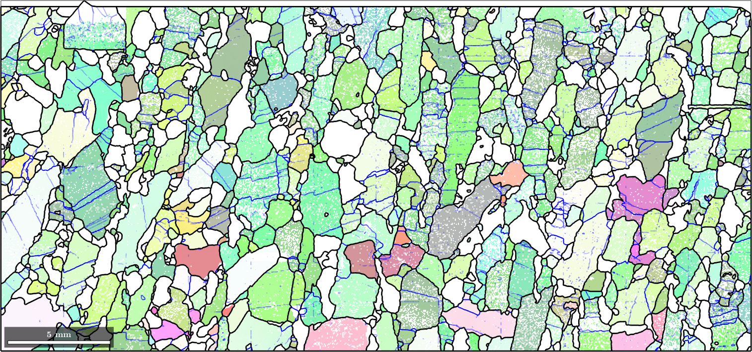
In the above plot we have marked all subgrain boundaries in blue and adjusted the transparency value according to the misorientation angle.
Misorientation Axes
When analyzing the misorientation axes of the subgrain boundary misorientations we need to distinguish whether we look at the misorientation axes in crystal coordinates or in specimen coordinates. Lets start with the misorientation axes in crystal coordinates which can directly be computed by the command axis.
% extract the Forsterite subgrain boundaries
subGB = grains('fo').innerBoundary;

% plot the misorientation axes in the fundamental sector
plot(subGB.misorientation.axis,'fundamentalRegion','figSize','small')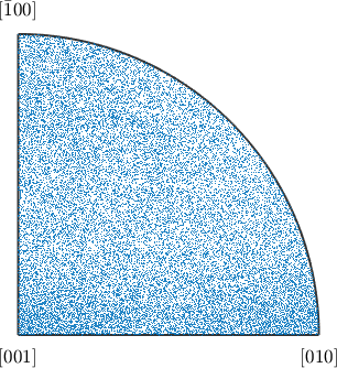
Obviously from the above plot it is not easy to judge about preferred misorientation axes. We get more insight if we compute the density distribution of the misorientation axes and look for local extrema.
% compute the density distribution of misorientation axes
density = calcDensity(subGB.misorientation.axis,'halfwidth',3*degree);

% plot them
plot(density,'figSize','small')
mtexColorbar

% find the two preferred misorientation axes
[~,hkl] = max(density,'numLocal',2); round(hkl)
ans = Miller (Forsterite)
size: 2 x 1
antipodal: true
h k l
0 0 1
0 7 1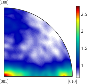
We find two preferred misorientation axes - (001) and (071). TODO: can this be interpreted?
The misorientation axis in specimen coordinates
The computation of the misorientation axis in specimen coordinates is a little bit more complicated as it is impossible using only the misorientation. In fact we require the adjacent orientations on both sides of the subgrain boundaries. We can find those by making use of the ebsdId stored in the grain boundaries. The command
oriGB = ebsd('id',subGB.ebsdId).orientationsoriGB = orientation (Forsterite → y↑→x)
size: 31909 x 2results in a \(N \times 2\) matrix of orientations with rows corresponding to the boundary segments and two columns for both sides of the boundary. The misorientation axis in specimen coordinates is again computed by the command axis
axS = axis(oriGB(:,1),oriGB(:,2),'antipodal')

% plot the misorientation axes
plot(axS,'MarkerAlpha',0.2,'MarkerSize',2,'figSize','small')
axS = vector3d (y↑→x)
size: 31909 x 1
antipodal: true
We have used here the option antipodal as we have no fixed ordering of the grains at the two sides of the grain boundaries. For a more quantitative analysis we again compute the corresponding density distribution and find the preferred misorientation axes in specimen coordinates
density = calcDensity(axS,'halfwidth',5*degree);
plot(density,'figSize','small')
mtexColorbar

[~,pos] = max(density)
annotate(pos)
pos = vector3d (y↑→x)
antipodal: true
x y z
0.193882 0.706069 0.681084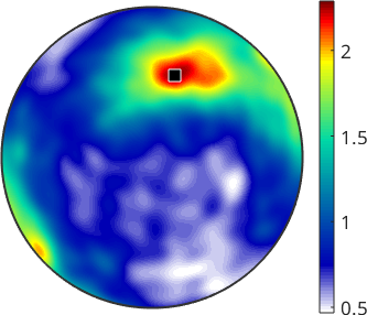
Tilt and Twist Boundaries
Subgrain boundaries are often assumed to form during deformation by the accumulation of edge or screw dislocations. In the first extreme case of exclusive edge dislocations the misorientation axis is parallel to the deformation line and within the boundary plane. Such boundaries are called tilt boundaries. In the second extreme case of exclusive screw dislocations the misorientation axis is the screw axis and is parallel to the boundary normal. Such boundaries are called twist boundaries.
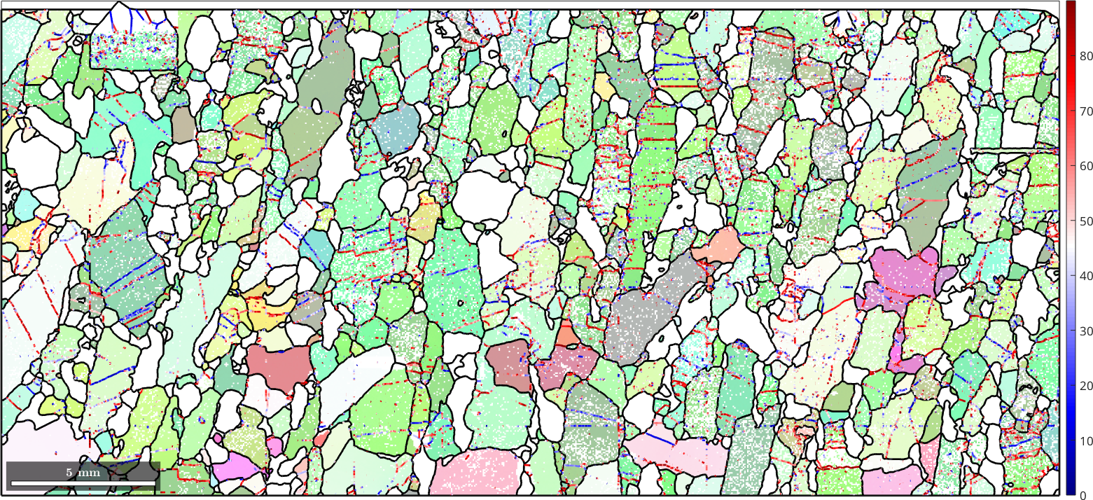
In the case of 2d-EBSD data one usually has not the full boundary information, but only the trace of the boundary with the measurement surface. Hence, it is impossible to distinguish tilt and twist boundaries. However, for twist boundaries misorientation axis must be normal to the boundary trace. This means, if the misorientation axis lays in the measurement plane and normal to the boundary trace, the boundary is quite likely to be a twist boundary. At the other hand, if the misorientation axis is parallel to the trace of a boundary, the boundary is quite likely to be a tilt boundary. We can be easily check the latter situation from our EBSD data, which allows us to exclude certain boundaries to be twist boundaries and to be most likely tilt boundaries To do so, we colorize in the following plot all subgrain boundaries according to the angle between the boundary trace and the misorientation axis. Blue subgrain boundaries are very likely tilt boundaries, while red subgrain boundaries are can be either tilt or twist boundaries.
plot(ebsd('fo'),color,'faceAlpha',0.5,'figSize','large')

% init override mode
hold on

% plot grain boundaries
plot(grains.boundary,'linewidth',2)

% colorize the subgrain boundaries according the angle between boundary
% trace and misorientation axis
plot(subGB,angle(subGB.direction,axS)./degree,'linewidth',2)
mtexColorMap blue2red
mtexColorbar

hold off