Although \(\varphi_2\) sections are most common to represent orientation distribution functions they heavily suffer from geometrical distortions of the orientation space. Lets illustrate this at a simple example. The following \(\varphi_2\) sections represent a hexagonal ODF composed from several unimodal components
% the ODF is defined at the bottom of this script to be secret during the first read :)
cs = crystalSymmetry.load('Ti-Titanium-alpha.cif');
odf = secretODF(cs);

plotSection(odf)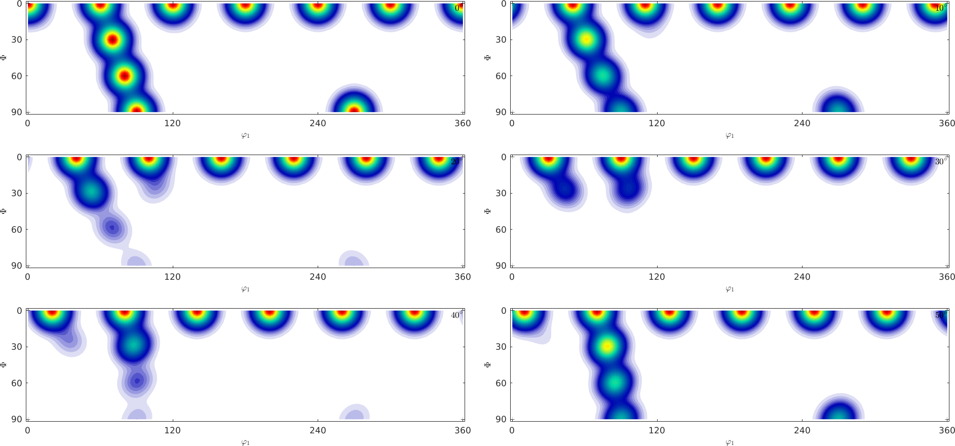
Try to answer the following questions:
- What is the number of components the ODF is composed of?
- What would the c-axis pole figure look like?
- What would the a-axis pole figure look like?
Most people find it difficult to find the correct answer by looking at \(\varphi_2\) sections, while it is much more easy by looking at \(\sigma\)-sections.
Lets consider an arbitrary orientation given by its Euler angles \((\varphi_1, \Phi, \varphi_2)\). Then its position in the c-axis pole figure is given by the polar coordinates \((\Phi,\varphi_1)\), i.e. it depends only on the first two Euler angles. The third Euler angle \(\varphi_2\) controls the rotation of the crystal around this new c-axis. This rotation around the new c-axis can be described by the angle between the a-axis with respect to some fixed reference direction. In the case of hexagonal symmetry this angle may vary between \(0\) and \(60\) degree.
The idea of sigma sections is to make a reasonable choice of this reference direction.
% define a sigma section
oS = sigmaSections(odf.CS,odf.SS,'sigma',0);

close all
plot(oS)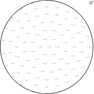
In the above plot each pixel corresponds to a unique orientation. Which is specified by the position of the c-axis being in the position of the pixel and the a-axis being aligned with the small arrow at this position. As an example lets consider the orientation
ori1 = orientation.map(cs.cAxis,vector3d.Z,cs.aAxis,vector3d.X)ori1 = orientation (Titanium → y↑→x)
Bunge Euler angles in degree
phi1 Phi phi2
30 0 0that maps the c-axis parallel to the z-direction and the a-axis parallel to the x-direction and the orientation
ori2 = orientation.map(cs.cAxis,vector3d.X,cs.aAxis,-vector3d.Z)ori2 = orientation (Titanium → y↑→x)
Bunge Euler angles in degree
phi1 Phi phi2
90 90 300that maps the c-axis parallel to the x-axis and the a-axis parallel to the z-axis.
hold on
% visualize the a-axes directions of ori1
quiver(ori1.symmetrise,ori1.symmetrise*cs.aAxis,'color','r','linewidth',2)

% visualize the a-axes directions of ori2
quiver(ori2.symmetrise,ori2.symmetrise*cs.aAxis,'color','green','linewidth',2)
hold off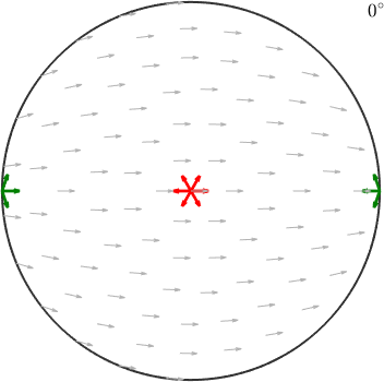
Accordingly, the first orientations appears right in the center while the second one appears at the position of the x-axis. The red and green arrows indicate the directions of the a-axes and align perfectly with the small background arrows.
In order to visualize orientations with different a-axis alignments we need to additional sections with rotated small arrows.
% a full sigma section plot
oS = sigmaSections(odf.CS,odf.SS);
plot(oS)

% some orientations
ori1 = orientation.byEuler(60*degree,40*degree,60*degree,cs);
ori2 = orientation.byEuler(200*degree,80*degree,110*degree,cs);
ori3 = orientation.byEuler(40*degree,0*degree,0*degree,cs);

hold on
quiver(ori1.symmetrise,ori1.symmetrise*cs.aAxis, 'color','red','linewidth',2)

quiver(ori2.symmetrise,ori2.symmetrise*cs.aAxis, 'color','green','linewidth',2)

quiver(ori3.symmetrise,ori3.symmetrise*cs.aAxis, 'color','blue','linewidth',2)
hold off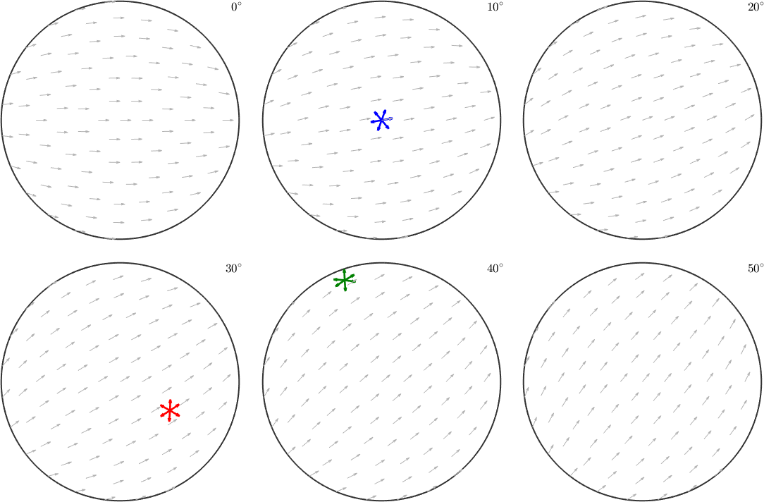
Note how the a-axes of the three orientations align with the small background arrows. Instead of the a-axes we may also visualize the crystal orientations directly within these sigma sections
% define hexagonal crystal shape
cS = crystalShape.hex(cs);

% plot the crystal shape into the sigma sections
ori = [ori1,ori2,ori3];
plotSection(ori,0.5.*(ori*cS),oS)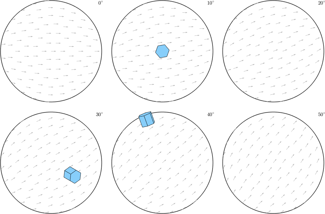
Lets come back to our initial secret ODF and visualize it in sigma sections
plotSection(odf,oS)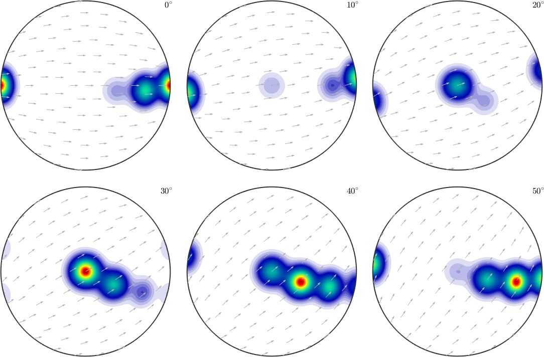
First of all we observe clearly 4 distinct components with the first one having its maximum for the c-axis parallel to the z-axis and the a-axis parallel to the y-axis. With the other three components the c-axis rotates toward the x-axis while the a-axis rotates towards the z-axis. Hence, we would expect in the c-axis a girdle from \(z\) to \(x\) and in the a-axis pole figure ...
plotPDF(odf,[cs.cAxis,cs.aAxis])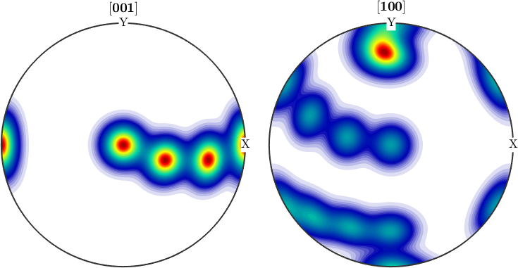
% They can be seen as the (001) pole figure split according to rotations
% about the (001) axis. Lets have a look at the (001) pole figure

plotPDF(odf,Miller(0,0,0,1,cs))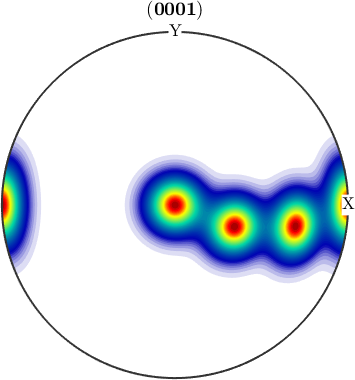
We observe three spots. Two in the center and one at 100. When splitting the pole figure, i.e. plotting the odf as sigma sections
plot(odf,'sections',6,'silent','sigma')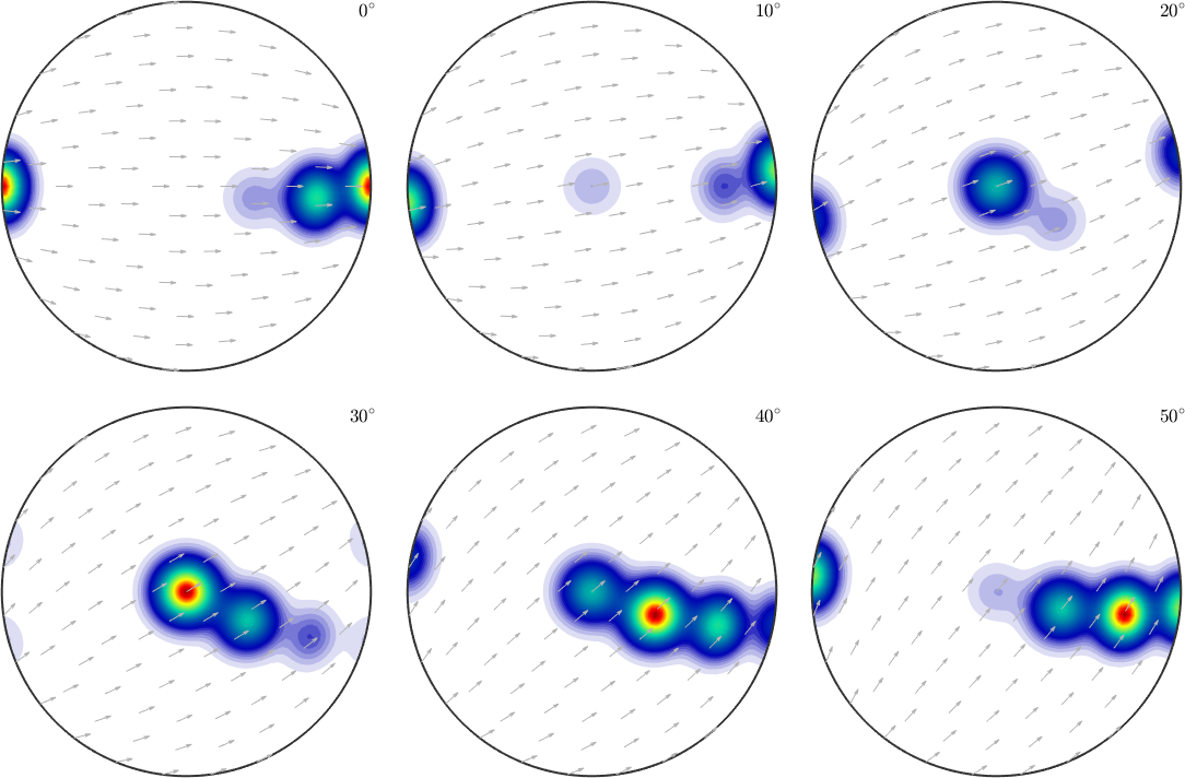
we can clearly distinguish the two spots in the middle indicating two radial symmetric portions. On the other hand the spots at (001) appear in every section indicating a fiber at position [001](100). Knowing that sigma sections are nothing else then the split (001) pole figure they are much more simple to interpret than usual \(\phi_2\) sections.
Customization
oS = sigmaSections(odf.CS,odf.SS);

% we may choose the crystal direction (10-10) as the reference direction
oS.h2 = Miller(1,0,-1,0,cs);

plotSection(odf,oS)

% we may even change the reference vector field
%oS.referenceField = S2VectorField.polar(xvector);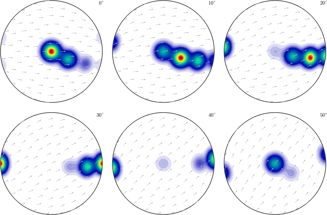
We may also change the pole figure we would like to split into sections.
% the pole figure we are going to split
oS.h1 =  Miller(1,0,-1,1,'hkil',odf.CS);

% the reference direction, needs to be orthogonal to h1
oS.h2 = Miller(-1,2,-1,0,odf.CS,'UVTW');

% since h1 is not a symmetry axis of the crystal we need to consider
% all rotations up to 360 degree
oS.omega = (0:20:340)*degree;

plot(odf,oS)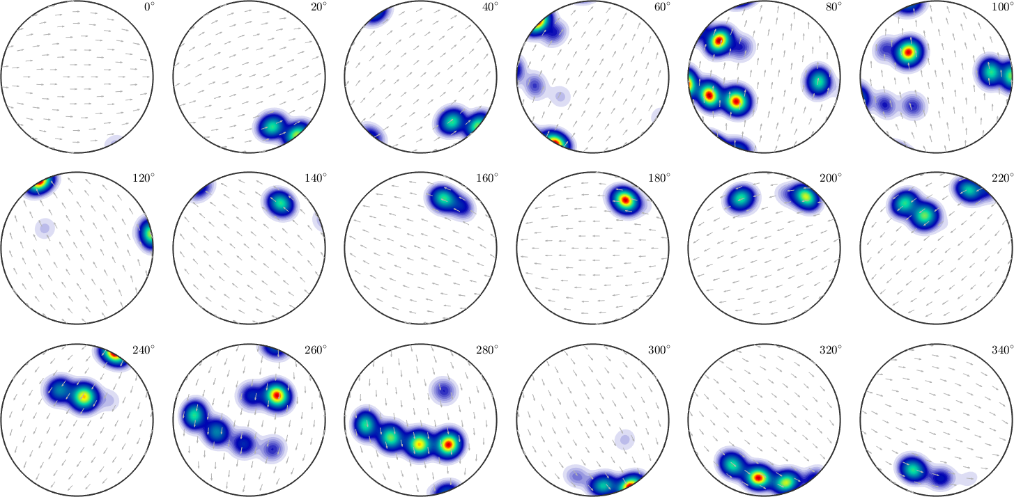
function odf = secretODF(cs)

ori = [orientation.byEuler(60*degree,0*degree,0*degree,cs),...
  orientation.byEuler(70*degree,30*degree,0*degree,cs),...
  orientation.byEuler(80*degree,60*degree,0*degree,cs),...
  orientation.byEuler(90*degree,90*degree,0*degree,cs)];

odf = unimodalODF(ori);

end